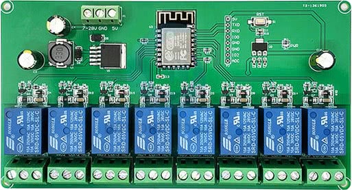
ESP-12F_Relay_X8

Product description
This is an 8-relay board with an ESP-12F.
Each relay has COM+NO+NC exposed. Product descriptions don't seem to specify maximum load.
The board can be powered either via 7-30VDC or via 5VDC via the screw terminals. Power the board with the screw terminals for flashing.
I bought it from: https://s.click.aliexpress.com/e/_DnEOi2r (affiliation link so i can make others like this, no guarantee it will continue to exist).
GPIO Header
This board has headers for a few GPIO pins on its ESP-12F.
| Pin | Comment |
|---|---|
| 5V | Do not use 5V for programming. Power via screw terminals. |
| TX | Exposed on board 3.3V level! UART0_TX |
| RX | Exposed on board 3.3V level! UART0_RX |
| GPIO0 | 3.3V level! (pulled up, connect to GND for programming) |
| GND | |
| GND | |
| GPIO2 | UART1_TX |
| ADC |
GPIO Pinout
Be aware that relay 1 and 6 will be momentarily toggled on during boot.
| Pin | Comment |
|---|---|
| GPIO0 | Relay 6 (high on boot) |
| GPIO2 | Exposed on board, (blue) LED on the ESP-12F |
| GPIO4 | Relay 7 |
| GPIO5 | Relay 8 |
| GPIO12 | Relay 3 |
| GPIO13 | Relay 4 |
| GPIO14 | Relay 2 |
| GPIO15 | Relay 5 |
| GPIO16 | Relay 1 (high on boot) |
Basic Config
esphome:
  name: relayboard

esp8266:
  board: esp12e

# Status LED
light:
  - platform: status_led
    name: "RelayBoard LED"
    restore_mode: ALWAYS_ON
    pin:
      number: GPIO02
      inverted: True

# 8 relay outputs, exposed as switches in Home Assistant
switch:
  - platform: gpio
    pin: GPIO16
    name: Relay1
    id: relay1
  - platform: gpio
    pin: GPIO14
    name: Relay2
    id: relay2
  - platform: gpio
    pin: GPIO12
    name: Relay3
    id: relay3
  - platform: gpio
    pin: GPIO13
    name: Relay4
    id: relay4
  - platform: gpio
    pin: GPIO15
    name: Relay5
    id: relay5
  - platform: gpio
    pin: GPIO00
    name: Relay6
    id: relay6
  - platform: gpio
    pin: GPIO04
    name: Relay7
    id: relay7
  - platform: gpio
    pin: GPIO05
    name: Relay8
    id: relay8