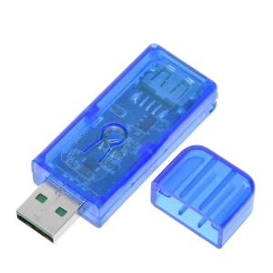
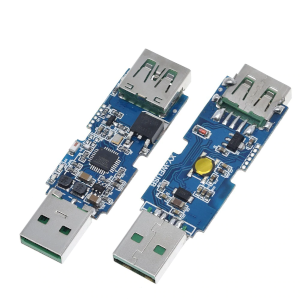
Sinilink XY-WFUSB USB Switch Relay
This device can be found on Aliexpress for about 5 USD.


Flashing
The case can be pried open without too much difficulty. Be careful to keep both halves as parallel as possible to not break the pins that hold them together.
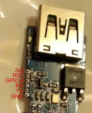
Flashing must be done by connecting an FTDI adapter to the 1.27 mm pads close to the USB female port. Here is the pinout:

The pads are small, so this is a bit tricky. I did it with some sewing pins stuck into dupont wires. It could be done as well connecting alternating pins from either side of the board.
GPIO0 has to be connected to GND to enter programming mode.
GPIO Pinout
| Pin | Function | Note |
|---|---|---|
| GPIO00 | User (Pad GPIO-0) | Pulled-up to HIGH, boot fails if pulled LOW |
| GPIO01 | User (Pad TX) | HIGH at boot, spits debug output at boot, boot fails if pulled LOW |
| GPIO03 | User (Pad RX) | HIGH at boot |
| GPIO04 | Toggle Button | Pin input LOW when button is pressed |
| GPIO05 | Relay and Red LED | USB socket power with LED is ON when pin output HIGH |
| GPIO14 | Green LED | LED is ON when pin output HIGH |
| GPIO16 | Blue LED | LED is ON when pin output HIGH |
Basic Config
The following configuration mimics this Tasmota template string.
The green LED is turned on when the relay is off and vice versa. The blue LED is used as the status LED. The button toggles the state of the relay.
I had to increase the ap_timeout, this board seems to take some time to connect to the WiFi.
substitutions:
  name: usb-relay
  friendly_name: "USB Relay"
  default_state: "RESTORE_DEFAULT_OFF"

esphome:
  name: ${name}
  friendly_name: "${friendly_name}"

esp8266:
  board: esp01_1m
  restore_from_flash: True

logger:

wifi:
  ssid: !secret wifi_ssid
  password: !secret wifi_password
  fast_connect: True
  power_save_mode: HIGH
  ap:
    ssid: "${friendly_name}"
    ap_timeout: 3min

captive_portal:

api:

ota:

time:
  - platform: homeassistant

# Blue LED
status_led:
  pin:
    number: GPIO16

# Relay
switch:
  - platform: gpio
    id: switch_relay
    pin: GPIO5

  # Green LED
  - platform: gpio
    pin: GPIO14
    id: green_led
    inverted: true # start on

  # Switch template to link relay and green LED states
  # LED is on when relay is off
  - platform: template
    id: relay
    name: "${friendly_name}"
    lambda: |-
      if (id(switch_relay).state) {
        return true;
      } else {
        return false;
      }
    turn_on_action:
      - switch.turn_on:
          id: green_led
      - switch.turn_on:
          id: switch_relay
    turn_off_action:
      - switch.turn_off:
          id: green_led
      - switch.turn_off:
          id: switch_relay

# Button
binary_sensor:
  - platform: gpio
    id: hardware_button
    pin:
      number: GPIO04
      mode: INPUT_PULLUP
      inverted: True
    on_press:
      - switch.toggle: relay

# WiFi Signal Sensor
sensor:
  - platform: wifi_signal
    name: "WiFi Status"
    update_interval: 60s

# Restart button
button:
  - platform: restart
    name: "Restart"
If the USB Relay controls a light, it can also be implemented like this:
output:
  # Relay
  - platform: gpio
    id: switch_relay
    pin: GPIO5

  # Green LED
  - platform: gpio
    pin: GPIO14
    id: green_led
    inverted: true # start on

  # Binary Output template to link relay and green LED states
  # LED is on when relay is off
  - platform: template
    type: binary
    id: relay
    write_action:
      if:
        condition:
          lambda: return state;
        then:
          - output.turn_on: switch_relay
          - output.turn_on: green_led
        else:
          - output.turn_off: switch_relay
          - output.turn_off: green_led

# Button
binary_sensor:
  - platform: gpio
    id: hardware_button
    pin:
      number: GPIO04
      mode: INPUT_PULLUP
      inverted: True
    on_press:
      light.toggle: "${name}"

light:
  - platform: binary
    name: "${friendly_name}"
    id: "${name}"
    output: relay