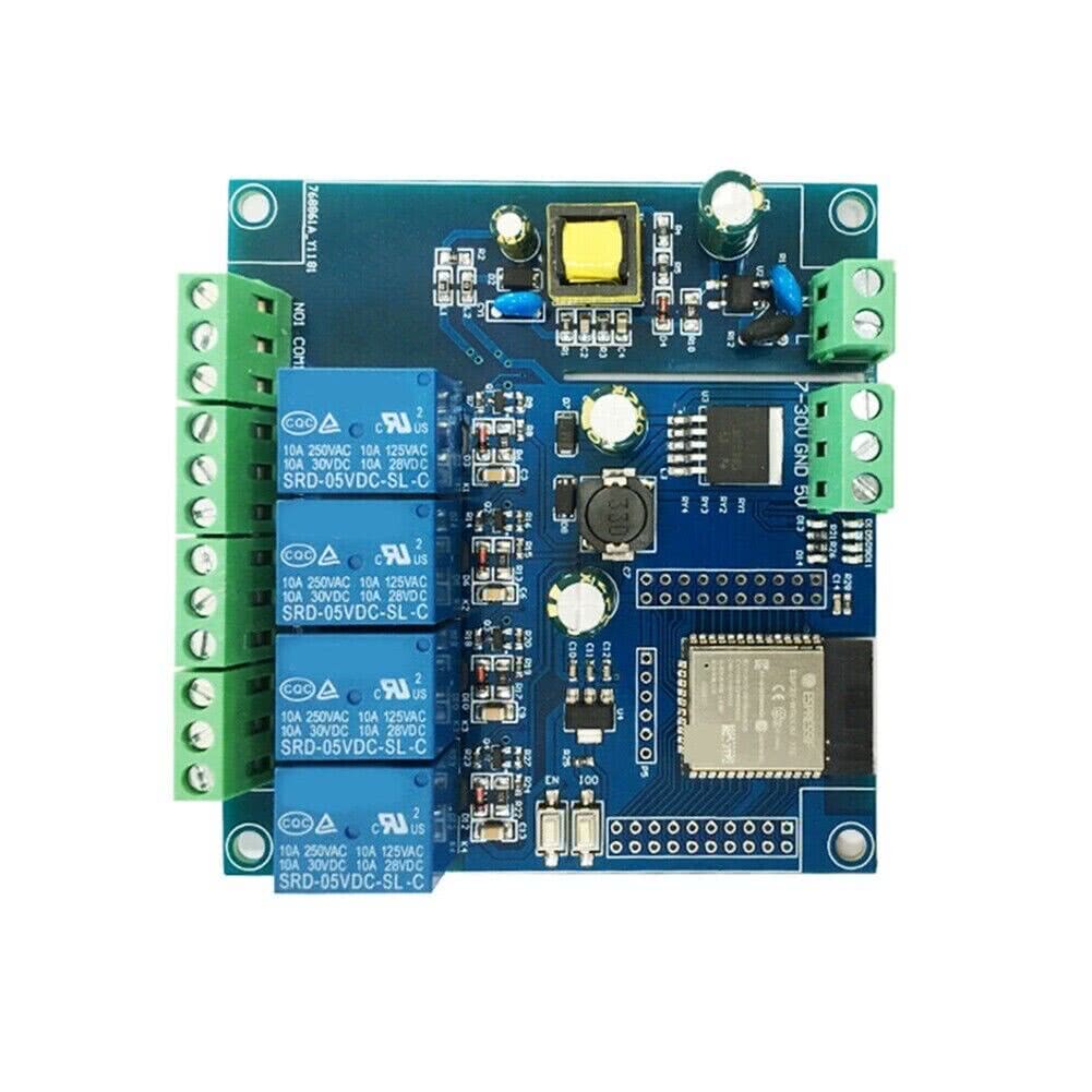
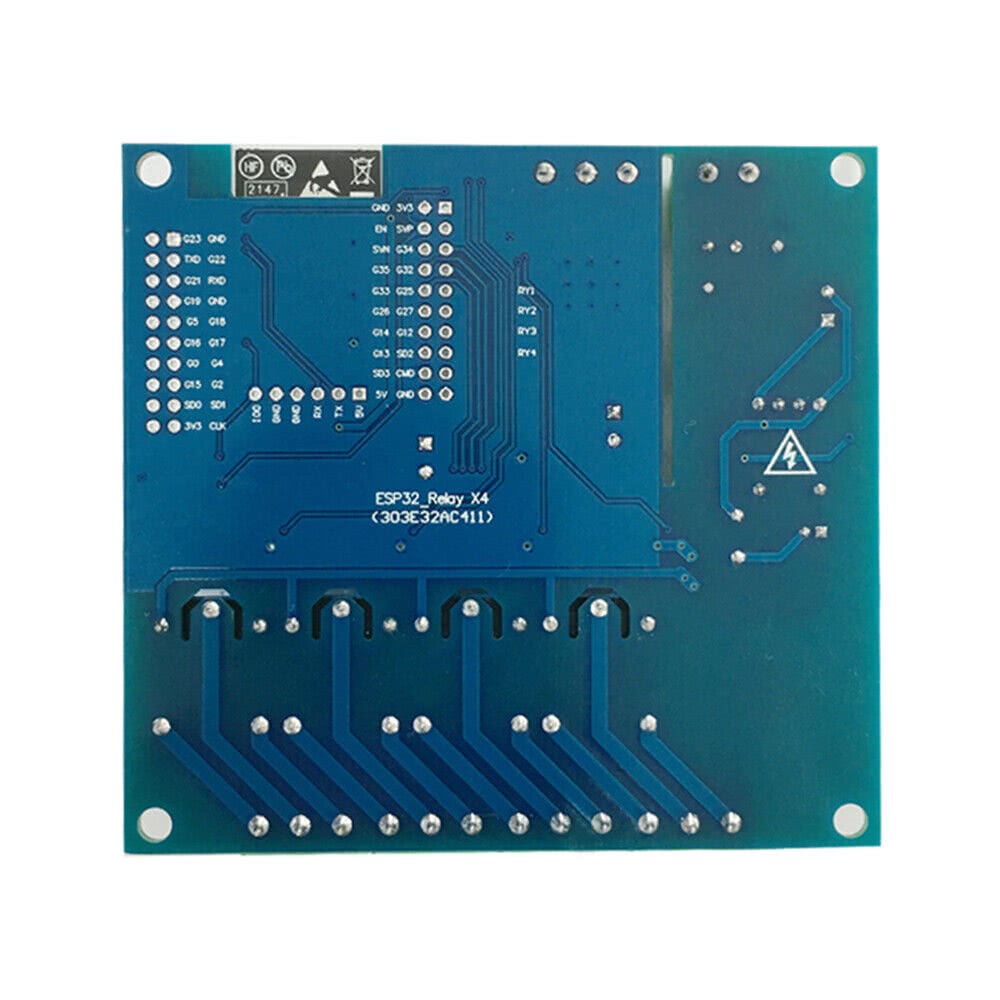
ESP32_Relay X4 (AC/DC powered)


Product description
This is a 4-relay board with an ESP32-WROOM-E that can be powered from either AC mains or a wide range of DC. The board can be powered either via 120-220VAC, 7-30VDC or 5VDC (separate connectors).
Each relay has COM+NO+NC exposed. The board also exposes a plethora of free GPIOs to use on solder pads.
Link: https://www.aliexpress.com/item/1005008762604101.html
Note: v1.1 of this board is nearly identical except the chip is an ESP32-WROOOM-32E
Pinout
This board has two double-row headers 10x2 for every GPIO pin on its ESP32 and a single row header for flashing. Programming can be done with 3.3V connected to 5V pin and GPIO0 connected to GND (via jumper or a push button). After flasing, if you want to test the board - it has to be powered properly via dedicated connectors, or via 5VDC applied to 5V ping. If you'll power it up with 3.3V on 5V pin - the MCU will brownout.
Programming header pinout
| Pin | Comment |
|---|---|
| 5V | Do not use 5V for programming |
| TX | Exposed on board 3.3V level! |
| RX | Exposed on board 3.3V level! |
| GND | |
| GND | |
| GPIO0 | 3.3V level! (Connected to a push button for programing) |
Internal pinout
| Pin | Function |
|---|---|
| GPIO23 | Status LED |
| GPIO32 | Relay #1 |
| GPIO33 | Relay #2 |
| GPIO25 | Relay #3 |
| GPIO26 | Relay #4 |
Basic Config
esphome:
  name: ac-dc-relay-x4
  friendly_name: ac-dc-relay-x4

esp32:
  board: esp32dev
  framework:
    type: esp-idf

switch:
  - platform: gpio
    pin: GPIO32
    name: "Relay 1"
  - platform: gpio
    pin: GPIO33
    name: "Relay 2"
  - platform: gpio
    pin: GPIO25
    name: "Relay 3"
  - platform: gpio
    pin: GPIO26
    name: "Relay 4"

status_led:
  pin: GPIO23