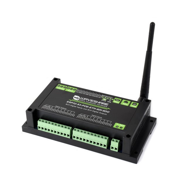
WAVESHARE ESP32-S3-ETH-8DI-8RO

Product description
This is a feature packed I/o board with an ESP32-S3-WROOM-1U-N16R8.
It has
- Powered by ESP32-S3 with dual-core Xtensa LX7 CPU up to 240 MHz
- Integrated 2.4 GHz Wi-Fi + Bluetooth LE with external antenna
- Ethernet port than can provide PoE power
- Isolated RS485 interface for Modbus sensors/modules
- Isolated CANbus interface
- 8 optocoupler isolated inputs
- 8 optocoupler isolated outputs
- External i2c header
- GPIO header for expansion (e.g. RS232, sensors)
- USB-C for power, firmware upload, and debugging. Can provide power to other devices with a jumper
- 7–36V wide-range input via screw terminal for industrial use
- Status indicators: buzzer, RGB LED, power, RS485 TX/RX
- ABS rail-mount enclosure for safe, easy installation
The board can be powered either via 7-36DC or via 5VDC (USB-C). Outputs provide current sinking up to 500ma
More information:
- Product page: https://www.waveshare.com/esp32-s3-eth-8di-8do.htm
- Wiki: https://www.waveshare.com/wiki/ESP32-S3-ETH-8DI-8RO
Basic Config
This config has Wi-Fi enabled by default. You cannot use both WiFi and Ethernet at the same time (ESPHome Ethernet documentation). In order to use Ethernet, uncomment the Ethernet block and comment the Wi-Fi blocks.
substitutions:
substitutions:
  device_name: waveshare-di8-do8
  device_comment: "WaveShare ESP32-S3-POE-ETH-8DI-8DO Device"
  friendly_name: "WaveShare DI8-DO8"

esphome:
  name: ${device_name}
  friendly_name: ${friendly_name}
  min_version: 2025.5.0
  comment: ${device_comment}
  name_add_mac_suffix: false
  on_boot:
    then:
      - pcf85063.read_time:
          id: pcf85063_time
# ==========================================================
# Board Configuration
# ==========================================================
# Module is ESP32-S3-WROOM-1U-N16R8 (16MB flash, 8MB PSRAM)
esp32:
  board: esp32s3box
  flash_size: 16MB
  framework:
    type: esp-idf

psram:
  mode: octal
  speed: 80MHz

# ==========================================================
# Core Configuration
# ==========================================================
logger:
  baud_rate: 0 #Change if serial logging
  level: WARN

api:

ota:
  - platform: esphome

# ==========================================================
# Network Configuration
# ==========================================================
 # Wi-FI or Ethernet can be enabled, not both concurrently.
wifi:
  ssid: !secret wifi_ssid
  password: !secret wifi_password

  # Enable AP when WiFi connection fails
  ap:
    ssid: "${friendly_name} AP"
    password: "12345678"

captive_portal:

## ethernet:
##   type: W5500
##   clk_pin: GPIO15
##   mosi_pin: GPIO13
##   miso_pin: GPIO14
##   cs_pin: GPIO16
##   interrupt_pin: GPIO12
##   reset_pin: GPIO39

web_server:
  port: 80

## # Bluetooth Tracker
## esp32_ble_tracker:

# ==========================================================
# Hardware Buses
# ==========================================================
# I2C
i2c:
  sda: GPIO42
  scl: GPIO41
  frequency: 100kHz
  id: i2cbus
  scan: false

# 8-bit expander that drives DO1..DO8
pca9554:
  - id: tca9554_hub
    address: 0x20

### RS485
##uart:
##  - id: modbus_uart
##    tx_pin: GPIO17
##    rx_pin: GPIO18
##    baud_rate: 9600
##    stop_bits: 1
##    data_bits: 8
##    parity: NONE

### CANbus
##canbus:
##  - platform: esp32_can
##    tx_pin: GPIO2
##    rx_pin: GPIO3
##    can_id: 4
##    bit_rate: 125kbps

# ==========================================================
# Accessories
# ==========================================================
# Real-time Clock
time:
  - platform: homeassistant
    id: ha_time
    on_time_sync:
      then:
        # Update the RTC when the synchronization was successful
        - pcf85063.write_time:
  - platform: pcf85063
    id: pcf85063_time

# Buzzer
output:
  - platform: ledc
    id: buzzer
    pin:
      number: GPIO46
      ignore_strapping_warning: true

rtttl:
  id: rtttl_buzzer
  output: buzzer
  gain: 30%

# RGB LED
light:
  - platform: esp32_rmt_led_strip
    id: rgb_led
    name: "RGB LED"
    chipset: WS2812
    rgb_order: RGB
    pin: GPIO38
    num_leds: 1

# ==========================================================
# Sensors
# ==========================================================
binary_sensor:
  - platform: gpio
    name: "Boot Button"
    pin:
      number: GPIO0
      ignore_strapping_warning: true
      mode:
        input: true
      inverted: true
    disabled_by_default: true

# --- Digital Inputs -----------------------------------------
  - platform: gpio
    id: di1
    name: "DI1"
    pin:
      number: GPIO4
      mode: INPUT_PULLUP
      inverted: true
    filters:
      - delayed_on_off: 10ms

  - platform: gpio
    id: di2
    name: "DI2"
    pin:
      number: GPIO5
      mode: INPUT_PULLUP
      inverted: true
    filters:
      - delayed_on_off: 10ms

  - platform: gpio
    id: di3
    name: "DI3"
    pin:
      number: GPIO6
      mode: INPUT_PULLUP
      inverted: true
    filters:
      - delayed_on_off: 10ms

  - platform: gpio
    id: di4
    name: "DI4"
    pin:
      number: GPIO7
      mode: INPUT_PULLUP
      inverted: true
    filters:
      - delayed_on_off: 10ms

  - platform: gpio
    id: di5
    name: "DI5"
    pin:
      number: GPIO8
      mode: INPUT_PULLUP
      inverted: true
    filters:
      - delayed_on_off: 10ms

  - platform: gpio
    id: di6
    name: "DI6"
    pin:
      number: GPIO9
      mode: INPUT_PULLUP
      inverted: true
    filters:
      - delayed_on_off: 10ms

  - platform: gpio
    id: di7
    name: "DI7"
    pin:
      number: GPIO10
      mode: INPUT_PULLUP
      inverted: true
    filters:
      - delayed_on_off: 10ms

  - platform: gpio
    id: di8
    name: "DI8"
    pin:
      number: GPIO11
      mode: INPUT_PULLUP
      inverted: true
    filters:
      - delayed_on_off: 10ms

# --- Digital Outputs ----------------------------------------
switch:
  - platform: gpio
    name: "DO1"
    id: do1
    pin:
      pca9554: tca9554_hub
      number: 0
      mode:
        output: true
    inverted: true

  - platform: gpio
    name: "DO2"
    id: do2
    pin:
      pca9554: tca9554_hub
      number: 1
      mode:
        output: true
    inverted: true

  - platform: gpio
    name: "DO3"
    id: do3
    pin:
      pca9554: tca9554_hub
      number: 2
      mode:
        output: true
    inverted: true

  - platform: gpio
    name: "DO4"
    id: do4
    pin:
      pca9554: tca9554_hub
      number: 3
      mode:
        output: true
    inverted: true

  - platform: gpio
    name: "DO5"
    id: do5
    pin:
      pca9554: tca9554_hub
      number: 4
      mode:
        output: true
    inverted: true

  - platform: gpio
    name: "DO6"
    id: do6
    pin:
      pca9554: tca9554_hub
      number: 5
      mode:
        output: true
    inverted: true

  - platform: gpio
    name: "DO7"
    id: do7
    pin:
      pca9554: tca9554_hub
      number: 6
      mode:
        output: true
    inverted: true

  - platform: gpio
    name: "DO8"
    id: do8
    pin:
      pca9554: tca9554_hub
      number: 7
      mode:
        output: true
    inverted: true